
VOLCANO TOPOGRAPHY
|
|
EOS Volcanology Slide Set #2
VOLCANO TOPOGRAPHY |
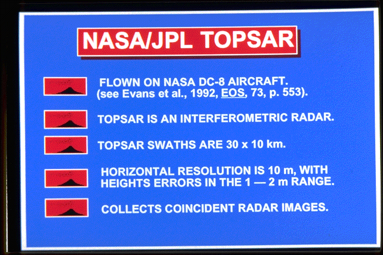 SLIDE #1 (111K)
 SLIDE #2 (125K)
 SLIDE #3 (108K)
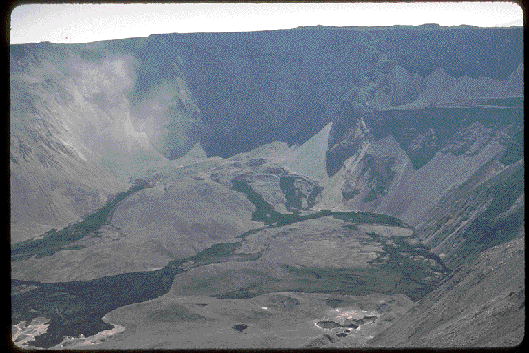 SLIDE #4 (120K)
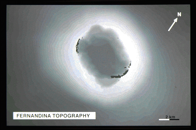 SLIDE #5 (118K)
 SLIDE #6 (91K)
 SLIDE #7 (165K)
 SLIDE #8 (92K)
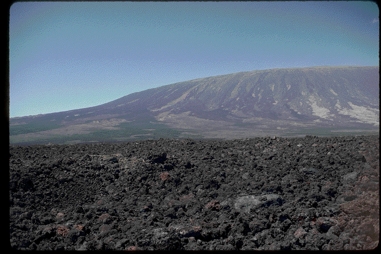 SLIDE #9 (128K)
 SLIDE #10 (166K)
 SLIDE #11 (147K)Return to Main EOS Volcanology Page